Interfacing LCD with ARM LPC2148
Hey guys, today we are going to interface our first peripheral device, other than led of course, which is a 16x2 LCD. LCD always has been an important part of an embedded project.
Some details about LCD-
 You guys know about Gnd, Vcc, Led+ and Led-. Make sure you connect them with right pins.
VEE pin is connected to variable resistor for contrast adjustment.
RS pin is Register select and used to select data or command mode. RS=0 is command and RS=1 is DATA.
R/W pin is to read or write from LCD. select 1 to write, 0 to read.
EN pin is Enable.
DB0 to DB7 are data pins.
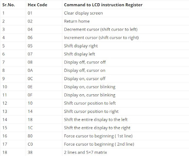
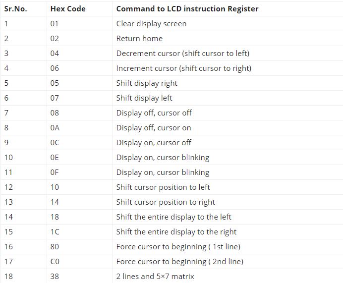
Commands for LCD-
How To Use-
LCD can be used in 4 bit mode so we only have to use 4 data pins and not all 8 of them. This helps in saving 4 pins of the controller for some other purposes. So let's just get to it.
My pin setup is as follows-
RS------> P1.16
R/W------>P1.17
EN------>P1.18
D4------>P1.19
D4------>P1.20
D4------>P1.21
D4------>P1.22
A) First we need to write the functions to send the command and data to the lcd.
1. void send_cmd (unsigned char cmd)
{
IO1CLR|=(1<<16); // clearing P1.16 so RS=0 because we are sending command here
IOCLR1|=(1<<17); // clearing P1.17 so R/W=0, therefore write operation
IO1SET|=cmd<<19; // our data pins are connected from P1.19 to P1.22
IO1SET|=(1<<18); // Set the enable pin
delay (); // wait a little, maybe 5 ms
IO1CLR|=(1<<18); // clear the Enable pin
delay(); // wait a little
IO1CLR|=cmd<<19; // clear the data pins for next data or command
}
Note- Our LCD commands are 8 bit long but as I mentioned that we are using only 4 pins of the lcd and the controller, so we have to break the commands in 4 bits and send them separately. Here is how to do that
2. void decode_cmd (unsigned char cmd)
{
unsigned char cmd_low, cmd_high; // defining cmd_low for lower 4 bits and cmd_high for higher 4 bits
cmd_high = (cmd>>4)&0x0f; // shift higher bits to lower position and make higher bits 0's
cmd_low = (cmd)&0x0f; // make higher bits 0's. cmd_low will only contain lower bits
send_cmd (cmd_high); // send upper 4 bits to lcd
send_cmd (cmd_low); // send lower 4 bits to lcd
}
3. Do the same thing with data- send it separately in 4 bits.
void send_data (unsigned char data)
{
IOSET1|=(1<<16); // setting P1.16 so RS=1 because we are sending data here
IOCLR1|=(1<<17); // clearing P1.17 so R/W=0, therefore write operation
IO1SET|=data<<19; // our data pins are connected from P1.19 to P1.22
IO1SET|=(1<<18); // Set the enable pin
delay (); // wait a little, maybe 5 ms
IO1CLR|=(1<<18); // clear the Enable pin
delay(); // wait a little
IO1CLR|=data<<19; // clear the data pins for next data or command
}
4. void decode_data (unsigned char data)
{
unsigned char data_low, data_high; // defining data_low for lower 4 bits and data_high for higher 4 bits
data_high = (data>>4)&0x0f; // same as cmd_high
data_low = (data)&0x0f; // same as cmd_low
send_data (data_high); // send upper 4 bits to lcd
send_data (data_low); // send lower 4 bits to lcd
}
B) Now we need to initialize LCD in 4 bit mode by sending some specific set of commands
void lcd_init (void)
{
decode_cmd(0x02); // cmd to initialize in 4 bit mode
decode_cmd (0x28); // cmd to initialize in 4 bit mode
decode_cmd (0x0c); // display off cursor on
decode_cmd (0x01); // clear the display
decode_cmd (0x80); // set the display in first row first column
}
C) Let's say if we want to write a whole string at once, we can write a function for that too
void send_string ( char *data)
{
while (*data) // while loop runs until last character of the string is reached
{
decode_data (*data++); // send data to lcd and increment pointer to string
}
}
That's it guys, now we are ready to write our main code and display any string on lcd.
code-
#include <lpc214x.h>
void delay (void)
{
for (int i=0; i<50; i++)
{
for (int j=0;j<50;j++)
{
{
/* do nothing here*/
}
}
}
}
void send_cmd (unsigned char cmd)
{
IOCLR1|=(1<<16); // clearing P1.16 so RS=0 because we are sending command here
IOCLR1|=(1<<17); // clearing P1.17 so R/W=0, therefore write operation
IOSET1|=cmd<<19; // our data pins are connected from P1.19 to P1.22
IOSET1|=(1<<18); // Set the enable pin
delay (); // wait a little, maybe 5 ms
IOCLR1|=(1<<18); // clear the Enable pin
delay(); // wait a little
IOCLR1|=cmd<<19; // clear the data pins for next data or command
}
void decode_cmd (unsigned char cmd)
{
unsigned char cmd_low, cmd_high; // defining cmd_low for lower 4 bits and cmd_high for higher 4 bits
cmd_high = (cmd>>4)&0x0f; //shift higher bits to lower position and make higher bits 0's
cmd_low = (cmd)&0x0f; // make higher bits 0's. cmd_low will only contain lower bits
send_cmd (cmd_high); // send upper 4 bits to lcd
send_cmd (cmd_low); // send lower 4 bits to lcd
}
void send_data (unsigned char data)
{
IOSET1|=(1<<16); // setting P1.16 so RS=1 because we are sending data here
IOCLR1|=(1<<17); // clearing P1.17 so R/W=0, therefore write operation
IOSET1|=data<<19; // our data pins are connected from P1.19 to P1.22
IOSET1|=(1<<18); // Set the enable pin
delay (); // wait a little, maybe 5 ms
IOCLR1|=(1<<18); // clear the Enable pin
delay(); // wait a little
IOCLR1|=data<<19; // clear the data pins for next data or command
}
void decode_data (unsigned char data)
{
unsigned char data_low, data_high; // defining data_low for lower 4 bits and data_high for higher 4 bits
data_high = (data>>4)&0x0f; // same as cmd_high
data_low = (data)&0x0f; // same as cmd_high
send_data (data_high); // send upper 4 bits to lcd
send_data (data_low); // send lower 4 bits to lcd
}
void send_string (char *data)
{
while (*data) // while loop runs until last character of the string is reached
{
decode_data (*data++); // send data to lcd and increment pointer to string
}
}
void lcd_init (void)
{
decode_cmd (0x02); // cmd to initialize in 4 bit mode
decode_cmd (0x28); // cmd to initialize in 4 bit mode
decode_cmd (0x0c); // display off cursor on
decode_cmd (0x80); // set the display in first row 0th column
}
int main ()
{
PINSEL2 = 0; // setting pinsel register for gpio function
IODIR1 = 0x00ff0000; // setting pins 16 to 23 as output
char hello[] = "HELLO WORLD"; // string we want to display on lcd
lcd_init (); // initialize the lcd
send_string (hello);
decode_cmd (0xc0); // set cursor to 2nd row 0th column
send_string ("test success");
}
That's it guys, we have successfully interfaced LCD with lpc2148.
subscribe for more tutorials.
WORKING CODE AND SIMULATION - Download here

Some details about LCD-

VEE pin is connected to variable resistor for contrast adjustment.
RS pin is Register select and used to select data or command mode. RS=0 is command and RS=1 is DATA.
R/W pin is to read or write from LCD. select 1 to write, 0 to read.
EN pin is Enable.
DB0 to DB7 are data pins.
Commands for LCD-
How To Use-
LCD can be used in 4 bit mode so we only have to use 4 data pins and not all 8 of them. This helps in saving 4 pins of the controller for some other purposes. So let's just get to it.
My pin setup is as follows-
RS------> P1.16
R/W------>P1.17
EN------>P1.18
D4------>P1.19
D4------>P1.20
D4------>P1.21
D4------>P1.22
A) First we need to write the functions to send the command and data to the lcd.
1. void send_cmd (unsigned char cmd)
{
IO1CLR|=(1<<16); // clearing P1.16 so RS=0 because we are sending command here
IOCLR1|=(1<<17); // clearing P1.17 so R/W=0, therefore write operation
IO1SET|=cmd<<19; // our data pins are connected from P1.19 to P1.22
IO1SET|=(1<<18); // Set the enable pin
delay (); // wait a little, maybe 5 ms
IO1CLR|=(1<<18); // clear the Enable pin
delay(); // wait a little
IO1CLR|=cmd<<19; // clear the data pins for next data or command
}
Note- Our LCD commands are 8 bit long but as I mentioned that we are using only 4 pins of the lcd and the controller, so we have to break the commands in 4 bits and send them separately. Here is how to do that
2. void decode_cmd (unsigned char cmd)
{
unsigned char cmd_low, cmd_high; // defining cmd_low for lower 4 bits and cmd_high for higher 4 bits
cmd_high = (cmd>>4)&0x0f; // shift higher bits to lower position and make higher bits 0's
cmd_low = (cmd)&0x0f; // make higher bits 0's. cmd_low will only contain lower bits
send_cmd (cmd_high); // send upper 4 bits to lcd
send_cmd (cmd_low); // send lower 4 bits to lcd
}
3. Do the same thing with data- send it separately in 4 bits.
void send_data (unsigned char data)
{
IOSET1|=(1<<16); // setting P1.16 so RS=1 because we are sending data here
IOCLR1|=(1<<17); // clearing P1.17 so R/W=0, therefore write operation
IO1SET|=data<<19; // our data pins are connected from P1.19 to P1.22
IO1SET|=(1<<18); // Set the enable pin
delay (); // wait a little, maybe 5 ms
IO1CLR|=(1<<18); // clear the Enable pin
delay(); // wait a little
IO1CLR|=data<<19; // clear the data pins for next data or command
}
4. void decode_data (unsigned char data)
{
unsigned char data_low, data_high; // defining data_low for lower 4 bits and data_high for higher 4 bits
data_high = (data>>4)&0x0f; // same as cmd_high
data_low = (data)&0x0f; // same as cmd_low
send_data (data_high); // send upper 4 bits to lcd
send_data (data_low); // send lower 4 bits to lcd
}
B) Now we need to initialize LCD in 4 bit mode by sending some specific set of commands
void lcd_init (void)
{
decode_cmd(0x02); // cmd to initialize in 4 bit mode
decode_cmd (0x28); // cmd to initialize in 4 bit mode
decode_cmd (0x0c); // display off cursor on
decode_cmd (0x01); // clear the display
decode_cmd (0x80); // set the display in first row first column
}
C) Let's say if we want to write a whole string at once, we can write a function for that too
void send_string ( char *data)
{
while (*data) // while loop runs until last character of the string is reached
{
decode_data (*data++); // send data to lcd and increment pointer to string
}
}
That's it guys, now we are ready to write our main code and display any string on lcd.
code-
#include <lpc214x.h>
void delay (void)
{
for (int i=0; i<50; i++)
{
for (int j=0;j<50;j++)
{
{
/* do nothing here*/
}
}
}
}
void send_cmd (unsigned char cmd)
{
IOCLR1|=(1<<16); // clearing P1.16 so RS=0 because we are sending command here
IOCLR1|=(1<<17); // clearing P1.17 so R/W=0, therefore write operation
IOSET1|=cmd<<19; // our data pins are connected from P1.19 to P1.22
IOSET1|=(1<<18); // Set the enable pin
delay (); // wait a little, maybe 5 ms
IOCLR1|=(1<<18); // clear the Enable pin
delay(); // wait a little
IOCLR1|=cmd<<19; // clear the data pins for next data or command
}
void decode_cmd (unsigned char cmd)
{
unsigned char cmd_low, cmd_high; // defining cmd_low for lower 4 bits and cmd_high for higher 4 bits
cmd_high = (cmd>>4)&0x0f; //shift higher bits to lower position and make higher bits 0's
cmd_low = (cmd)&0x0f; // make higher bits 0's. cmd_low will only contain lower bits
send_cmd (cmd_high); // send upper 4 bits to lcd
send_cmd (cmd_low); // send lower 4 bits to lcd
}
void send_data (unsigned char data)
{
IOSET1|=(1<<16); // setting P1.16 so RS=1 because we are sending data here
IOCLR1|=(1<<17); // clearing P1.17 so R/W=0, therefore write operation
IOSET1|=data<<19; // our data pins are connected from P1.19 to P1.22
IOSET1|=(1<<18); // Set the enable pin
delay (); // wait a little, maybe 5 ms
IOCLR1|=(1<<18); // clear the Enable pin
delay(); // wait a little
IOCLR1|=data<<19; // clear the data pins for next data or command
}
void decode_data (unsigned char data)
{
unsigned char data_low, data_high; // defining data_low for lower 4 bits and data_high for higher 4 bits
data_high = (data>>4)&0x0f; // same as cmd_high
data_low = (data)&0x0f; // same as cmd_high
send_data (data_high); // send upper 4 bits to lcd
send_data (data_low); // send lower 4 bits to lcd
}
void send_string (char *data)
{
while (*data) // while loop runs until last character of the string is reached
{
decode_data (*data++); // send data to lcd and increment pointer to string
}
}
void lcd_init (void)
{
decode_cmd (0x02); // cmd to initialize in 4 bit mode
decode_cmd (0x28); // cmd to initialize in 4 bit mode
decode_cmd (0x0c); // display off cursor on
decode_cmd (0x80); // set the display in first row 0th column
}
int main ()
{
PINSEL2 = 0; // setting pinsel register for gpio function
IODIR1 = 0x00ff0000; // setting pins 16 to 23 as output
char hello[] = "HELLO WORLD"; // string we want to display on lcd
lcd_init (); // initialize the lcd
send_string (hello);
decode_cmd (0xc0); // set cursor to 2nd row 0th column
send_string ("test success");
}
That's it guys, we have successfully interfaced LCD with lpc2148.
subscribe for more tutorials.
WORKING CODE AND SIMULATION - Download here

Interfacing LCD with ARM LPC2148
 Reviewed by Controllerstech
on
June 05, 2017
Rating:
Reviewed by Controllerstech
on
June 05, 2017
Rating:
Reviewed by Controllerstech
on
June 05, 2017
Rating:


No comments: