I2C LCD in STM32
As promised, today I am going to interface LCD to STM32 using an I2C device (PCF8574). PCF8574 can be used as a port extender, to which we will connect LCD. If you haven't read my previous post about I2C go HERE.


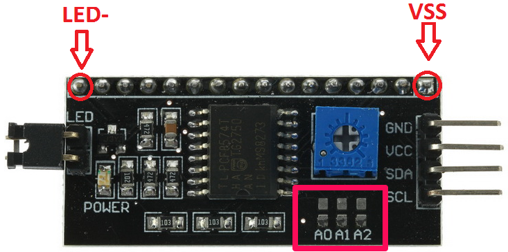
As you can see above PCF8574 has 4 input pins GND, VCC, SDA, SCL and 16 output pins. We will connect our LCD to these 16 pins.
ADDRESSING of PCF8574:-
The higher nibble of PCF8574 address is 0100 and this is fixed. But lower nibble can be modified according to our convenience.
The question is why we need to modify lower nibble? Well you generally don't but as I mentioned in my previous article that we can connect upto 128 devices on the same line of I2C and let's say we want to connect two different LCDs on the same I2C line, than we can't use two PCF8574 with same addresses and we need to modify one of them.
So how do we modify the address?
To change the address we are provided with A0, A1 and A2 pins.
By default these three pins are high so the address by default is 01001110 which is 0x4E. To change the address of this device, you have to connect any/all of these three pins to ground, which is provided just above them. So let's say you connected A0 to ground, new address will be 01001100 which is 0x4B. In this manner, we can connect upto 8 LCDs to the same line.
I want to point to one more thing here, the last bit of the address is kept 0 intentionally, because this bit is responsible for read(0)/ write(1) operation.
Connecting LCD to PCF8574:-
As shown in the figure above, first pin of the device is Vss which is pin 1 of LCD. So all you have to do is connect first pins of the LCD to Vss above and rest will connect accordingly.
Starting with Vss as first pin, connection is as follows:-

1 ---> Vss
2 ---> Vcc
3 ---> Vee
4 ---> RS ---> p0
5 ---> R/W ---> p1
6 ---> En ---> p2
7 ---> DB0
8 ---> DB1
9 ---> DB2
10 ---> DB3
11 ---> DB4 ---> p4
12 ---> DB5 ---> p5
13 ---> DB6 ---> p6
14 ---> DB7 ---> p7
15 ---> LED+
16 ---> LED-
Some Insight into the Code:-
First of all we have to create functions for LCD command and data.
command function
void lcd_send_cmd (char cmd)
   {
        char data_u, data_l;
 uint8_t data_t[4];
 data_u = cmd&0xf0;    // select only upper nibble
 data_l = (cmd<<4)&0xf0;    // select only lower nibble
 data_t[0] = data_u|0x04;  //en=1, rs=0
 data_t[1] = data_u;  //en=0, rs=0
 data_t[2] = data_l|0x04;  //en=1, rs=0
 data_t[3] = data_l;  //en=0, rs=0
 HAL_I2C_Master_Transmit (&hi2c1, 0x4E, (uint8_t *) data_t, 4, 100);
   }
The above function will send the command to the device to which our LCD is connected. As we are using 4 bit LCD mode, we have to send command in two parts first upper than lower. Both parts are sent along enable pin 1 and than with enable pin 0.
When Data is OR(|) with 0x04 which implies that P2 (En) pin is high and P0 (RS), P1(R/W) are low for the command and write operation.
In the second case data is sent alone so En, RS, R/W are all low.
data function
void lcd_send_data (char data)
   {
        char data_u, data_l;
 uint8_t data_t[4];
 data_u = cmd&0xf0;    // select only upper nibble
 data_l = (cmd<<4)&0xf0;    // select only lower nibble
 data_t[0] = data_u|0x05;  //en=1, rs=1
 data_t[1] = data_u|0x01;  //en=0, rs=1
 data_t[2] = data_l|0x05;  //en=1, rs=1
 data_t[3] = data_l|0x01;  //en=0, rs=1
 HAL_I2C_Master_Transmit (&hi2c1, 0x4E, (uint8_t *) data_t, 4, 100);
   }
The above functions ends the data to the device to which our LCD is connected. We have to send data in two parts first upper than lower. Both parts are sent along enable pin 1 and than with enable pin 0.
Data is OR(|) with 0x05 which implies that P2 (En) and P0 (RS) pin are high , P1(R/W) is low for the data and write operation.
In second case data is OR(|) with 0x01 to make only RS pin high and all others low.
THE CODE IS AT THE END OF THE POST
RESULT :-

TO Download full working code, VISIT
http://controllerstech.com/i2c-lcd-in-stm32/
CHECK OUT THE VIDEO BELOW
http://controllerstech.com/i2c-lcd-in-stm32/
CHECK OUT THE VIDEO BELOW
I2C LCD in STM32
 Reviewed by Controllerstech
on
July 12, 2017
Rating:
Reviewed by Controllerstech
on
July 12, 2017
Rating:
Reviewed by Controllerstech
on
July 12, 2017
Rating:


No comments: