SPI in STM32
I have written many posts about interfacing I2C devices with STM32 but there are some devices which require only SPI to work i.e. SD card reader, TFT display etc. So today in this post, we are going to learn how to use SPI with STM32.

SPI (Serial Peripheral Interface) generally requires 4 wires as shown above. The names are as follows:-
SCK --> Serial Clock
MOSI --> Master out Slave In is used to send data to slave
MISO --> Master In Slave Out is used to receive data from slave
CE/CS --> Chip Select is used for selecting the slave
SPI is not very different from I2C. It just require more wires and the process of selecting the slave is a little different. In order to enable a slave device, we need to pull the CS pin low and after our read or write is complete, just pull the pin high again. This will disable the slave device.
So before start setting up the CubeMx, Let's check the datasheet of ADXL345 to understand the requirements for the SPI.
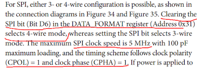
According to the figure above, We need to setup SPI with clock speed less than 5MHz and also CPOL =1 and CPHA =1. I will be using the 4 wire mode so let's set it up.. Below is the screenshot of the SPI setup window

We are using following to write data:-
NOTE that in data[0], address is OR with 0x40. This is for multibyte writing. It informs ADXL that we want to transfer more than one byte in a single transmission. According to ADXL datasheet, this byte should be high if you want to do that.

Here we are reading using the following steps:-
NOTE that address is OR with 0x80 and 0x40. That's because according to ADXL datasheet, If we want to read data, we need to set the last bit HIGH and also for multibyte read/write the 6th bit must be HIGH


SPI (Serial Peripheral Interface) generally requires 4 wires as shown above. The names are as follows:-
SCK --> Serial Clock
MOSI --> Master out Slave In is used to send data to slave
MISO --> Master In Slave Out is used to receive data from slave
CE/CS --> Chip Select is used for selecting the slave
SPI is not very different from I2C. It just require more wires and the process of selecting the slave is a little different. In order to enable a slave device, we need to pull the CS pin low and after our read or write is complete, just pull the pin high again. This will disable the slave device.
HOW TO
I am going to show you working with an actual hardware and because of lack of many SPI devices, I will work with whatever I have and that is ADXL345. I have already wrote a tutorial about How to use this device with I2C. Do check it out because I am not going to explain the register part but only focus on How to read and write data using SPI.So before start setting up the CubeMx, Let's check the datasheet of ADXL345 to understand the requirements for the SPI.

According to the figure above, We need to setup SPI with clock speed less than 5MHz and also CPOL =1 and CPHA =1. I will be using the 4 wire mode so let's set it up.. Below is the screenshot of the SPI setup window

Some Insight into the CODE
ADXL WRITE FUNCTION
...
void adxl_write (uint8_t address, uint8_t value)
{
 uint8_t data[2];
 data[0] = address|0x40;  // multibyte write
 data[1] = value;
 HAL_GPIO_WritePin (GPIOB, GPIO_PIN_6, GPIO_PIN_RESET);  // pull the cs pin low
 HAL_SPI_Transmit (&hspi1, data, 2, 100);  // write data to register
 HAL_GPIO_WritePin (GPIOB, GPIO_PIN_6, GPIO_PIN_SET);  // pull the cs pin high
}
We are using following to write data:-
- pull the CS low to enable the slave
- transmit the address to which we want to write data
- transmit the data
- pull the CS pin high to disable the slave
NOTE that in data[0], address is OR with 0x40. This is for multibyte writing. It informs ADXL that we want to transfer more than one byte in a single transmission. According to ADXL datasheet, this byte should be high if you want to do that.

ADXL READ FUNCTION
....
void adxl_read (uint8_t address)
{
 address |= 0x80;  // read operation
 address |= 0x40;  // multibyte read
 uint8_t rec;
 HAL_GPIO_WritePin (GPIOB, GPIO_PIN_6, GPIO_PIN_RESET);  // pull the pin low
 HAL_SPI_Transmit (&hspi1, &address, 1, 100);  // send address
 HAL_SPI_Receive (&hspi1, data_rec, 6, 100);  // receive 6 bytes data
 HAL_GPIO_WritePin (GPIOB, GPIO_PIN_6, GPIO_PIN_SET);  // pull the pin high
}
Here we are reading using the following steps:-
- pull the CS low to enable the slave
- transmit the address from where we want to read data
- receive data. 6 bytes in this case
- pull the CS pin high to disable the slave
NOTE that address is OR with 0x80 and 0x40. That's because according to ADXL datasheet, If we want to read data, we need to set the last bit HIGH and also for multibyte read/write the 6th bit must be HIGH

ADXL INITIALISATION FUNCTION
...
void adxl_init (void)
{
 adxl_write (0x31, 0x01);  // data_format range= +- 4g
 adxl_write (0x2d, 0x00);  // reset all bits
 adxl_write (0x2d, 0x08);  // power_cntl measure and wake up 8hz
}
To DOWNLOAD full CODE, visit
CHECK OUT THE VIDEO BELOW
SPI in STM32
 Reviewed by Controllerstech
on
February 14, 2019
Rating:
Reviewed by Controllerstech
on
February 14, 2019
Rating:
Reviewed by Controllerstech
on
February 14, 2019
Rating:


No comments: