STM32 ETHERNET CONNECTION
This tutorial is the start of the Ethernet series in STM32. Today we will simply see how to configure the Hardware.
For some of the MCUs, this will be as easy as the default setup, but for others, this part could be very complicated. Specially the Cortex M7 Series MCUs, where the cacheable region causes data coherency issues.
So I will try to explain the process in the best possible way. To better understand the result of different settings, I would suggest you to watch the Video at the end of this post.
CubeMX Configuration
Ethernet Configuration
There are many types of configurations available with different MCUs. Some MCUs let you configure the memory in the CubeMX, while others don't. Some of the Boards have the MII Hardware, while other have RMII.
Below is the picture of two (out of many) possible configurations

- The LEFT hardware uses the RMII pinout, while the RIGHT one is using MII pinout.
- On the LEFT one we have the option to choose the PHY Address. This should be set to 0, if you are using the on board LAN Port, and it should be 1 in case of the external module.
- On the RIGHT side, the MCU is letting us configure the memory for DMA descriptors, and the Rx Buffer.
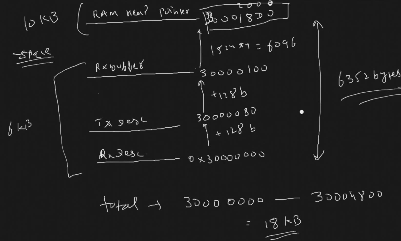
- Assuming that each DMA Descriptor takes 32 bits (MAXIMUM Possible), the RX Descriptor and Tx Descriptor have the size of 128 Bytes (32x4).
- The Memory between them is spaced accordingly.
- The Rx Buffer have the size of 1524x4 (Rx DMA Descriptor Length).
- The memories are allocated in the SRAM region, where we can modify the properties later in the MPU.
LWIP Configuration
The LightWeight IP can be enabled in the middleware section. If the MCU does not let you enable it, make sure the cache (DCache and ICache) are enabled.
The most of the Configuration in the LWIP remains same. Except, some MCUs let us choose the address for the Heap.
The most of the Configuration in the LWIP remains same. Except, some MCUs let us choose the address for the Heap.
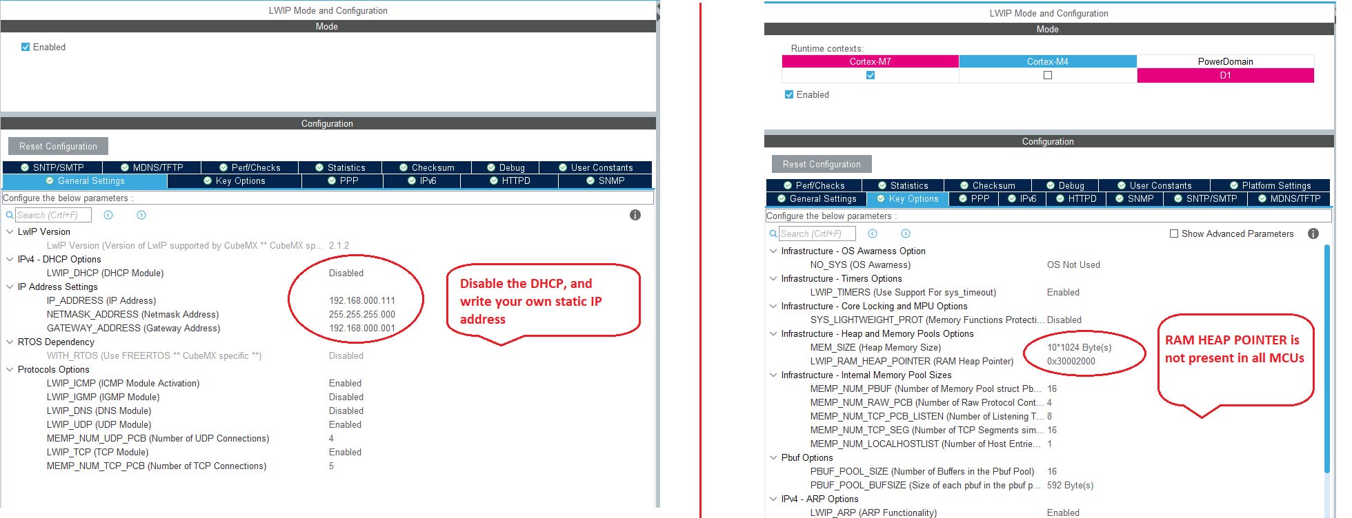
- Here we are going to disable the DHCP, and configure a static IP for our ethernet module.
- On the RIGHT, I am using 10KB memory for the Heap.
- This 10 KB is enough for our few applications in the beginning. Later we will increase it if needed to.
- Other than this, some MCUs will allow to fix the location for this Heap.
- The location is at an offset of 0x2000 in the SRAM, and the calculation for the same is shown below.
MPU Configuration
Now we have the DMA Descriptors in the SRAM Region. And this is why we need to configure the MPU.
If your MCU didn't let you choose the memory region, then probably you don't need to do it. But for the others, this is a must, or else you will get hardfault.
Remember that during the configuration, we set up everything in the SRAM (0x30000000). The total size of the RAM was around 18 KB. So we will configure the MPU keeping this information in mind.
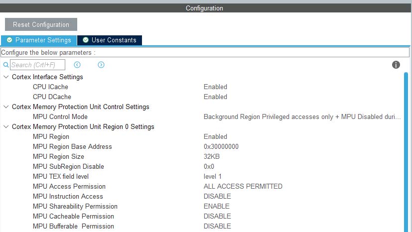
- Here we have selected the 32 KB region, since it's the least size available after 16 KB. And our region is 18 KB.
- The rest of the configuration is to set the region as non-cacheable region.
- This would prevent the cache coherency issue between the CPU and the DMA.
- This is explained in the cortex M7 playlist, so do check that out.
THE CODE
Since this tutorial is more focused on connection part, there is not much in the code.
We will just test the ping to our IP Address, and the code for the same is shown below.
/* USER CODE BEGIN 0 */

extern struct netif gnetif;

/* USER CODE END 0 */

...........MAIN..........

  while (1)
  {
    /* USER CODE END WHILE */

    /* USER CODE BEGIN 3 */

	  ethernetif_input(&gnetif);

	  sys_check_timeouts();
  }
RESULT
Below is the result from the ping test.
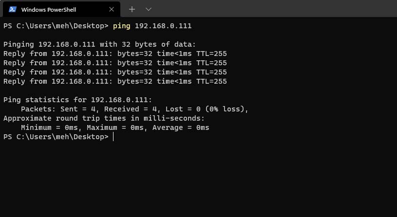 You can see the ping is working on the IP Address that we set during the configuration.
Check out the video below
To DOWNLOAD THE FULL CODE, VISIT
STM32 ETHERNET CONNECTION
 Reviewed by Controllerstech
on
October 04, 2021
Rating:
Reviewed by Controllerstech
on
October 04, 2021
Rating:
Reviewed by Controllerstech
on
October 04, 2021
Rating:


No comments: